Home
A Low Cost Thermal Peak Detection Charger
By Stefan Vorkoetter Introduction The electric model aircraft and car industries have produced a bewildering array of field chargers for NiCd motor battery packs. These range from simple 6 or 7 cell chargers consisting of a resistor and mechanical timer, to more complex chargers with peak detection, cycling, and the ability to handle 36 cell packs. The resistor/timer type of charger is cheap, but it is has two drawbacks: it might not fully charge the pack in the allotted time, or it might overcharge the pack. The more complex chargers have none of these drawbacks, but they are very expensive. The charger described in this article can charge packs of 4 to 7 cells with capacities ranging from 600mAh to 2Ah. The charger automatically begins charging when a pack is connected. It charges at a (nearly) constant current (adjustable), and terminates the charge when the pack begins to get warm (a NiCd pack begins to warm up when it has reached full charge). An LED indicates that charging is in progress. The Circuit 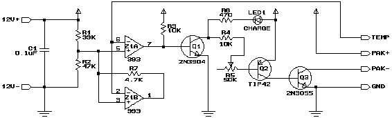 Figure 1 The circuit for the charger (Figure 1) is simple. Z1A is a comparator which compares the voltage on its two inputs and produces a high output when the + input (pin 5) is higher than the - input (pin 6), and a low output otherwise. R1 and R2 form a voltage divider, presenting a fixed voltage (about 7V) to pin 5. A pair of thermistors (TR1 between the PAK+ and TEMP terminals, and TR2 between the TEMP and GND terminals; see Figure 2) form another voltage divider which presents a voltage to pin 6. This voltage is proportional to the temperature difference between TR1 and TR2. When TR1 is within 10°C of TR2, this voltage is below 7V, and the output of Z1A turns on Q1. This causes current to flow through Q2, R5, and R4, turning Q2 on. This in turn causes Q3 to conduct, resulting in current flow through the NiCd pack connected between the PAK+ and PAK- terminals. The amount of current flowing through Q3 (and thus the pack) is determined by the current flowing through Q2, which in turn is determined by the setting of R5. The current can range from about 2A to 5A. While Q1 is on, current will also flow through LED1 and R6, thus illuminating LED1 to indicate that charging is in progress. As the temperature of TR1 rises, the voltage at pin 6 rises. When the temperature of TR1 exceeds that of TR2 by 10°C or more, pin 6 will exceed 7V, and Z1A will turn off Q1, Q2, and Q3, terminating the charge. Z1B performs the same comparison as Z1A, but its output is used to provide hysteresis (the current flowing into the base of Q1 pulls Z1As output too low for it to perform this function). When Z1B goes low, current flows through R7, lowering the voltage at pin 5 to about 1.4V. This ensures that the charger will not switch back on as the pack cools off (unless it cools to about 50°C below ambient). The only way to restart the charge is to disconnect the pack being charged. This will disconnect TR1, causing pin 6 to go to 0V, which will turn the charger back on. Since there is now no pack connected, no current will flow through Q3, even though the CHARGE LED is lit. When a pack with a sufficiently cool TR1 is plugged in, charging will recommence. TR1 and TR2 are identical thermistors. Their resistance is 10KW at 25°C, and the resistance increases or decreases by about 4% for each 1°C fall or rise in temperature (the actual rate of decrease and increase varies with temperature). TR2 is installed in the charging cable near the charging plug to measure ambient temperature. TR1 is installed in the battery pack to measure pack temperature. By using two thermistors, the charger will shut off based on the temperature rise instead of the absolute temperature (otherwise the pack will be overcharged on a cold day or undercharged on a hot day). Connectors and Cables I use 4-pin computer power supply connectors for charging my packs. My packs are all wired permanently into my planes, so this connector does not need to handle the motor current. Even if you connect your packs to your planes with connectors (eg. Sermos), I suggest each pack have a separate charge connector, thus reducing wear and tear on the more critical power connectors. I use the connector with the male housing (and female pins) in the plane, and the female/male connector on the charger. Computer power supply splitter cables are a good source of these connectors. I use the red and yellow leads for the battery + and - connections, and the two black leads for the thermistor (TR1). 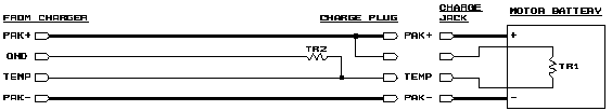 Figure 2 Figure 2 illustrates how the cable, connectors, and battery pack should be wired. The PAK+ and PAK- conductors should be 18ga or 16ga, since they must handle up to 5A. The GND and TEMP conductors can be thinner since they handle less than 3mA. For the 12V+ and 12V- inputs to the charger, use a two conductor 18ga or 16ga cable terminated with large clips suitable for connection to a car battery. Lamp cord is good for this. As the diagram implies, I have a separate thermistor in each of my packs. If you wish, you can use a temperature probe that is permanently connected to the charging cable, and insert this probe into the pack being charged. If you do this, you will need to install a normally-open START push-button between the TEMP and GND terminals, since the charger will not reset automatically with TR1 connected. Construction The circuit is designed to be installed in a Radio Shack project case (see parts list). Any suitably sized enclosure with a metal lid (or an all-metal enclosure) will do. R5 is glued to the component side of the board, with short lengths of wire connecting it to the appropriate pads. The lid of the case is drilled for R5 and LED1. The potentiometer is then installed in the appropriate hole, and this holds the board in place inside the case. 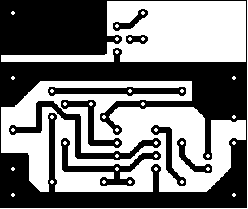 Figure 3 Figure 3 represents the full-sized printed circuit pattern for the charger. 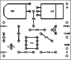 Figure 4 Figure 4 illustrates component placement on the board. Solder short lengths of wire to the appropriate terminals of R5. Glue R5 to the board, ensuring that R5s shaft is in line with the holes for LED1, and solder the leads. Install LED1, paying attention to polarity. The negative lead (usually indicated by a dot, flat spot, or shorter lead on the LED) is furthest from R5. The LED should be installed so it is high enough above the board to protrude through the corresponding hole that youll make for it in the case. Transistor Q2 should be laid flat on the board. A piece of aluminum channel, about 1.5 long and the width of Q2 should be placed on the copper side of the board, extending past the end of the board. Hold Q2, the board, and the aluminum channel together with an appropriate sized bolt. Ensure that the channel does not short circuit any traces. Install the remaining components, ensuring that none of them stick up high enough to interfere with the case once the board is installed. Transistor Q1 should have its rounded side facing R3. I suggest you use a socket for Z1, because it is easily damaged by soldering, and hard to remove if it is damaged. Install the socket, with pin 1 at the top left corner. Transistor Q3 should be installed on a hefty heatsink on the outside of the case and connected to the rest of the circuit with wires. The emitter of Q3 connects to the point marked E and the base to the point marked B. Use 16ga or 18ga wire for the emitter-to-E connection. Connect the charging cable to the circuit. Connect the PAK+, TEMP, and GND leads as marked on the board. Connect the PAK- lead to the collector of Q1 (the case). Connect the supply leads to the circuit at the points marked 12V+ (red) and 12V- (black). Install everything in the case. The circuit board occupies the left half of the case. The heat sink for Q3 is installed on the right half of the front panel. The heat sink for Q2 extends past the circuit board, underneath the top-right quarter of the case. LED1 protrudes through a vinyl grommet, providing more contrast. Testing and Calibration Connect the power leads to a 12V source (eg. a car battery). The LED should light immediately. Connect a 50KW potentiometer between the PAK+ and TEMP leads, with the resistor set at the half way point. The LED should stay lit. Slowly decrease the resistance. When the resistance reaches approximately 10K (assuming 20°C room temperature), the LED should go out. The LED should stay off even as you increase the resistance again. Temporarily disconnecting and reconnecting the potentiometer should cause the LED to light once again. To calibrate the charging current, use an ammeter in line with the PAK+ lead (an extra pair of 4-pin connectors is handy for this). Monitor the current when charging a depleted pack (the current will reduce towards the end of the charge, especially when charging 7 cell packs). Note the settings of R5 required for different currents and mark them on the case if you wish. When using the charger for the first time, monitor it carefully. Feel the pack from time to time (dont touch the thermistor though or your body heat will terminate the charge). The pack should barely start to warm up before charging stops. I'd Like to Hear from You If you build this circuit (or not), let me know what you think. If you have problems, I may be able to help you, but be sure to supply a detailed description. I can be reached at: Stefan Vorkoetter 8150 Concession 4 R.R.#3 Moorefield, Ontario N0G 2K0 or on the Internet at: smvorkoetter@maplesoft.on.ca Parts List The following table lists all the parts needed. Radio Shack part numbers are provided for those parts available there. The thermistors used in the prototype are from Radio Shack, although almost any thermistor with a 3% to 5% resistance drop per 1°C temperature rise will do.
*Notes: If you cannot obtain an appropriately sized potentiometer, Radio Shack 271-1716 will do, but youll need a larger case. You can also use a 100kW potentiometer, which will provide a wider current range (about 1A to 5A). If you cannot find an appropriate heat sink, you can get away without it if you use an all-metal case such as Radio Shack 270-239. |
||||||||||||||||||||||||||||||||||||||||||||||||||||||||||